Video 1: Group Rube Goldberg setup and brief explanation
2.Video
of your RG group in action
a.Failed attempt
b.Successful attempt
Video 2: Group Rube Goldberg Fail
Video 3: Fail again
Video 4: The ultimate fail...
We've been having minor tweaks to take care of, and every time we fixed something, another thing would go wrong. So unfortunately, we don't have a success video (so far).
This week’s blog sheet will
be both individual and group.
Your blogsheet 13 tasks:
1.Provide
the updated computer drawing for your individual RG setup.
2.Explain
your setup.
3.Provide
photos of the circuit and setup.
4.Provide
at least 2 new videos of your setup in action, one being a failed attempt.
5.What
failures did you have? How did you overcome them?
6.Group
task: Explain your group RG setup.
7.Group
task: Video of a test run of your group RG.
---------------------------------------------
AJ:
1.Provide
the updated computer drawing for your individual RG setup.
Image: Computer drawing setup
2.Explain
your setup.
A solar panel will start the
circuit when a cover is lifted from it from Andrew’s machine. Once the solar
panel is revealed to a light source (room lighting), the voltage will transfer to
an op amp and will then trigger a relay. Once the relay switches, the motor
will turn on. A string will be attached to the motor and a toy car; when
spinning, the toy car will charge at a balloon with a needle attached at a
slight angle. The balloon will pop, starting a domino effect. I plan on adding
a second motor to my circuit to help stop it after I start Vince’s machine. The
idea is to pull a component out of the breadboard (i.e. one of the resistors),
so that way it becomes an open circuit and stops my motors from running.
3.Provide
photos of the circuit and setup.
Image: Part of setup
4.Provide
at least 2 new videos of your setup in action, one being a failed attempt.
Video: Relay was going crazy when I used a new motor (3V)
Video: Plan B motor
Video: Mini test run (sorta failed)
I was able to obtain a smaller motor as shown in last week, however my motor went missing. So over the weekend I decided to go buy two motors, that way I have my own. However, when I tried connecting either of them to my original layout, the relay went crazy. I'm going to be figuring out this problem this week.
5.What
failures did you have? How did you overcome them?
My current issue is having my new motor spin. Not sure why, but the relay was just buzzing and my motor didn't spin at all. I've adjusted the voltage input, but was either getting nothing or the same buzzing sound. I haven't figured out a way to solve this yet due to lack of time. I'll be looking over it this week.
1.Provide
the updated computer drawing for your individual RG setup.
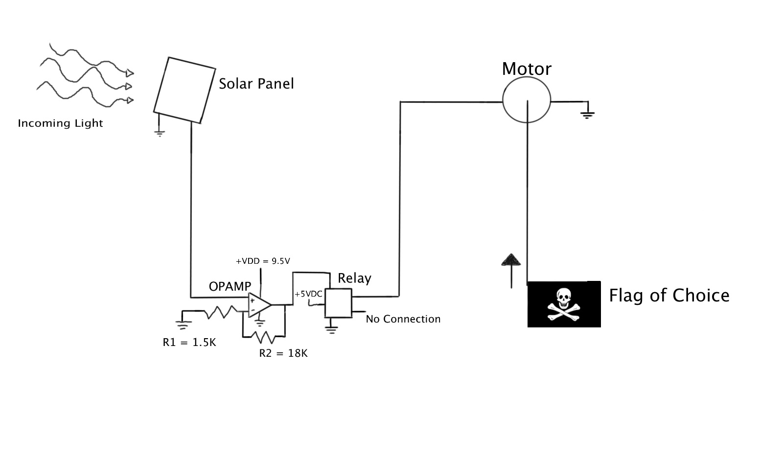
Image: Andrew's computer pic
2.Explain
your setup.
Initially the solar panel will be covered that way the
circuit will not be functioning. Once the solar panel becomes uncovered it will
transform the light into a small voltage, which will be amplified by the OpAmp
enough to trigger the relay to switch. Once the relay switches, the +5VDC will
be applied to the motor, which will turn it on and raise the flag (and
hopefully trigger the next circuit to activate.) Once the flag has been raised
to the top the motor will lift an object (a chunk of cement) off the limit
switch that will turn off the motor. Also, the +5VDC applied to the motor might
need to be calibrated (changed) slightly. It will probably be more like +3VDC
this way the motor doesn’t run too fast and mess something up. We want a slow
and controlled motion.
3.Provide
photos of the circuit and setup.
Image: Circuit set up
Image: Whole set up
4.Provide
at least 2 new videos of your setup in action, one being a failed attempt.
Video: Test Run
Video: Test run 2
5.What
failures did you have? How did you overcome them?
The
one thing that had to be adjusted was the voltage being applied to the motor,
at first it was too low and the motor wouldn’t even spin. This is a simple
problem to fix, you just have to increase the voltage slowly until you get to a
voltage that comfortably starts and keeps the motor spinning. Other then that,
I didn’t have too many problems
1.Provide
the updated computer drawing for your individual RG setup.
2.Explain
your setup.
The setup is pretty much the same
with only a few changes
The first change I made was the
addition of a solar panel to power the circuit instead of a force sensor. This
change occurred after I was still having trouble providing enough power to the
relay. Instead of providing power the force sensor was shorting the entire
circuit. The second change I made was changing my mechanics a little bit I
added a plastic cup attached to a string at the end of the ramp setup. The
string is attached on two different ends when the ball falls in the cup it will
do two things at once. On one end the sudden drop will pull the cover that is
placed over the solar panel starting the next machine. The other end of the
string will be attached to a small cardboard piece that when pulled will block
the light source on my solar panel turning off my motor.
3.Provide
photos of the circuit and setup.
Image: Motor/cardboard trigger
Image: Solar panel as new power source
Image; Full setup
4.Provide
at least 2 new videos of your setup in action, one being a failed attempt.
Video: Success run
Video: Failed run
5.What
failures did you have? How did you overcome them?
the big failure I had was getting
the force sensor to power my circuit. After several different setups and
getting the same result of shorting my circuit I decided to change to a solar
panel as my power source. This new power source worked perfectly and provided
the power I needed.
The second issue I faced was how to
turn off my circuit when complete I also tried to incorporate my force sensor
but again ran in to the issue of shorting out my circuit to early. I solved
this issue by changing my mechanics and rigging a cup to a string that will
pull down a small cardboard piece over my light source turning off my circuit.
A solar panel will become uncovered and the signal amplified
by an opamp, which will then trigger a relay to switch. Once the relay
switches, power will be delivered to a motor which will raise the flag. Then,
as the flag reaches the top, the motor will do two things. First, it will lift
a small piece of cement off a switch which will cause the motor to stop.
Secondly, it will remove the covering on AJ's solar panel and trigger her
circuit. This signal will be amplified as well by an opamp which will trigger a
relay delivering power to a motor. The motor will spin pulling a car across and
end up popping a balloon, which will then cause a chain reaction of dominos to
fall and eventually uncover the light
source that will activate Vince's circuit. The light source will be absorbed by
another solar panel which will, again, be amplified by an opamp and trigger a
relay. This will then provide power to a motor pulling a stopper releasing a
ball. The ball will then roll down a ramp and into a cup, which will then fall
of the table, pulling a piece of paper off the next solar panel and it will
then trigger the next circuit.
2.Group
task: Video of a test run of your group RG.
Video: Test run of group RG (failed)
We have a lot of tweaking to do for our group RG. We're currently working on fixing our own RG and making sure ours starts the next RG.
This week’s blog sheet will
be individual but you will post it on your group blog.
Your individual Rube Goldberg
(RG) setup should satisfy the following:
1.Use
at least 2 of the following components:
a.Transistor
b.OPAMP
c.Relay
d.Temperature sensor
e.Photosensor
f.Motor
g.Display
h.Strain gauge
i.Speaker
j.Microphone
k.Solar panel
2.Use
a new circuit: It can be a modification to one of our lab circuits.
3.Let
your system complete its task in no shorter than 10 seconds.
4.Make
sure you are compatible with your preceding and following RG stage.
Vince:
1.Provide
the computer drawing for your individual RG setup.
2.Explain
your setup.
The whole device is triggered by an
object landing on the force sensor. The input voltage goes through the oamp and
is multiplied by a non-inverting amplifier. This new input voltage is sent to
the relay. On one end is a led that is already on on the other is a motor
turned off. When the relay is triggered the motor turns on. This begins winding
a string attached to a small cardboard flap that is keeping the ball on top of
the ramp. The flap is removed and the ball rolls down the ramp triggering the
next device.
3.Provide
photos of the circuit and setup.
Image 1: Starting setup with force sensor as trigger
Image 2: Add LED to one end of relay
Image 3: Full set up
Image 4: Test one of entire set up
4.Provide
at least 2 videos of your setup in action, one being a failed attempt.
5.What
failures did you have? How did you overcome them?
One of the
major issues I have had is being able to use the force sensor to trigger the
relay. The problem is getting the input voltage high enough to trigger the
relay. I am trying different resistor combinations in a non-inverting amplifier
set up.
1.Provide the computer drawing for
your individual RG setup.
Image 1: Schematic idea #1
Image 2: Schematic idea #2
Image 3: Physical Rube Goldberg setup
2.Explain your setup.
Idea #1: A
solar panel will start the circuit when it is revealed to a light source from Andrew's machine. The capacitor will build up and the capacitor voltage will start the dc motor. With Idea #2, the voltage from the solar panel will transfer to an op amp, which will help trigger the relay. When the relay switches, it will turn on the 6V dc motor.
The motor will begin to spin, pulling a car that is attached to a wire. On the
front car, there is a needle. The car will drive into a balloon, popping it
with the needle, and hope that there will be enough force from the balloon pop
to start a domino effect (the balloon and the first domino will be touching
each other). At the end, the last domino will fall onto the force sensor of the
next Rube Goldberg machine.
Update: Decided to go with Idea #2
3.Provide photos of the circuit and
setup.
Image: Breadboard layout of Idea #2
Image: Breadboard with solar panel of Idea #2
4.Provide at least 2 videos of your
setup in action, one being a failed attempt.
Video 1: AJ's failed test run
F
Video 2: AJ's successful test run
5.What failures did you have? How did
you overcome them?
I was having issues starting up my motor; since it's a bigger motor, I
need to supply enough voltage to make it spin. I might have to add in an opamp (non-inverting). I wanted to use a photosensor to start the circuit, but had to use a solar panel instead. Before I connected the motor at the end, I was measuring about 6.5 V, which is enough to make the motor spin. But when I connected the motor, the voltage significantly drops to around 35 mV. It's becoming a reoccurring issue; probably something simple to fix though. Update: I was able to make a smaller motor run compared to the larger motor. I switched the large motor out for the small one since Andrew wasn't using his anymore for his machine (as of today at least). I fixed the values of the resistors to have a higher gain to trigger the relay and move the motor. However, now I need to make the physical part of my machine and test it out this week.
1.Provide the computer drawing for
your individual RG setup.
2.Explain your setup.
Initially the solar panel will be covered that way the
circuit will not be functioning. Once the solar panel becomes uncovered it will
transform the light into a small voltage, which will be amplified by the OpAmp
enough to trigger the relay to switch. Once the relay switches, the +5VDC will
be applied to the motor which will turn it on and raise the flag (and hopefully
trigger the next circuit to activate.) The only change that might be made is to
install a current limiting resister between the motor and relay.
3.Provide photos of the circuit and
setup.
Image: Andrew's breadboard layout
Image: Andrew's nifty wheel :)
4.Provide at least 2 videos of your
setup in action, one being a failed attempt.
Video 3: Andrew's failed Test Run
Video 4: Andrew's Success Test Run
5.What failures did you have? How did
you overcome them?
I needed to play around with the resistor values to get a high enough gain to move the crane setup. I also switched out my motor because the crane will be more efficient to pull the string and raise the flag.