Wednesday:
1. What is the role of A/B switch? If you are on A, would B still give you a voltage?
The role of the A/B switch is to signify
which supply the V and mA meters are connected. If you’re on A, B would still
give you a voltage; it doesn’t matter if it’s on independent or tracking.
2. In each channel, there is a current specification (either 0.5 A or 4 A). What does that mean?
This means that there is an adjustable
power supply from 0-24 V, hence up to 0.5 A, and a fixed 5 V supply up to 4 A. The
current specification allows the Constant Current indicator to light if there
is a unit that doesn’t meet the specification and can be rejected.
3. Your power supply has two main operation modes for A and B channels; independent and tracking. How do those operation work? (Video)
Video 1: Using the power supply to see the differences of switching from
different modes for A and B
In independent mode, A and B each supply
0-24 V up to 0.5 A. The operating controls for the two are independent of each
other and can be use either individually or simultaneously.
In tracking mode, the B supply tracks the
voltage the A supply. It can be used in series or parallel. In series, A and B
supplies are connected in series, which allows a single output of 0-48 V at up
to 0.5 A. In parallel, A and B supplies are in parallel and allows a single output of 0-24 V at up to 1 A.
4. Can you generate +30 V using a combination of the power supply outputs? How? (Photo)
Yes, you can generate +30V by having A and B in series tracking mode. If the voltage for A is set to 15 V, then the output voltage should be 30 V.
 |
| Image 1: Multimeter measured at 37.36 V |
5. Can you generate -30 V using a combination of the power supply outputs? How? (Photo)
Yes, if you flip around the prongs to get the
opposite reading. You can also obtain -30 V by grounding the positive terminal of A and the positive lead of A should be connected into the negative terminal of B.
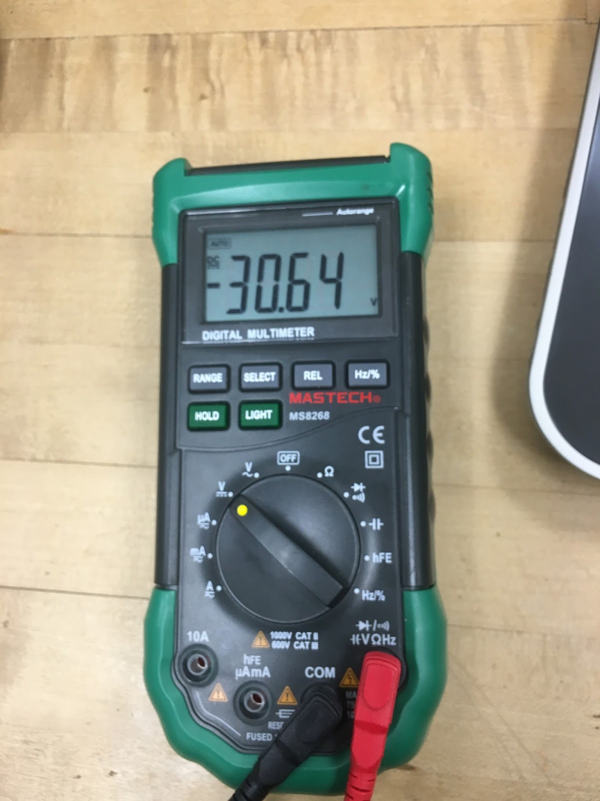 |
| Image 2: Multimeter measured at -30.64 V |
6. Can you generate +10 V and -10 V at the same time using a combination of the power supply outputs? How? (Photo)
Yes, by having both A and B supplies are set to 10 V in independent mode and by having the power supply wired in series. The positive and negative lead are connected opposite from each other; being said, connecting the red wire to the second power supply gives you 10 V while connecting the red wire to the negative terminal gives you -10 V. Pictures are provided below.
 |
| Image 3: First value measured: +10 V |
 |
| Image 4: Second value measured: -10 V |
 |
| Image 5: Our setup to show how to get +10 V and -10 V at the same time on the DMM |
7. Apply 5V to a 100 Ω resistor and measure the current by using the DMM (remember the setup in DC 3). Compare the reading with the current meter reading on the power supply. At what angle of the current knob makes the LED light on? If you keep on decreasing the current limit, what happens to the voltage and current? (Video)
On the power supply, we measured 20 mA and on the DMM, we measured 44.83 mA. The angle of the current knob that makes the LED light on is a little over 180 degrees. If you keep decreasing the current limit, the voltage and current both decrease; obtaining a negative current value at one point.
If it’s fixed, the current shows at 0 mA.
Video 2: Our setup to see what the maximum current value is
(the light turns on if it reaches over maximum)
8. Where is the fuse for the power supply? What is it for?
The fuse for the power supply is
located on the back of the power supply. It is used to prevent the power supply from being damaged if it is overloaded.
9. Where is the fuse for the DMM? What is it for?
The fuse for the DMM is on the bottom left
hand corner. It’s for breaking the circuit if a current exceeds a safe level.
10. What is the difference between 2W and 4W resistor measurements?
The difference between a 2W resistor and a 4W
resistor is that the 2W resistor allows a maximum of 500 V dc or ac rms while
the 4W resistor allows a maximum of 250 V dc or ac rms. The 4W resistor is also more accurate than the 2W resistor.
11. How would you measure current that is around 10 A using DMM?
Using the DMM, you would measure
the current by placing the positive lead beneath the negative. Our picture shows 0 mA because we didn't meet the requirements at 4W.
 |
| Image 6: Showing how where the leads are placed on the DMM |
Thank you for letting me comment! ;)
ReplyDelete- 2W vs 4W is not really accurate. W there is the wire.