Blog sheet week 5
1. Functional check: Oscilloscope manual page 5. Perform the functional check (photo).
 |
| Image 1: Functional check on oscilloscope |
 |
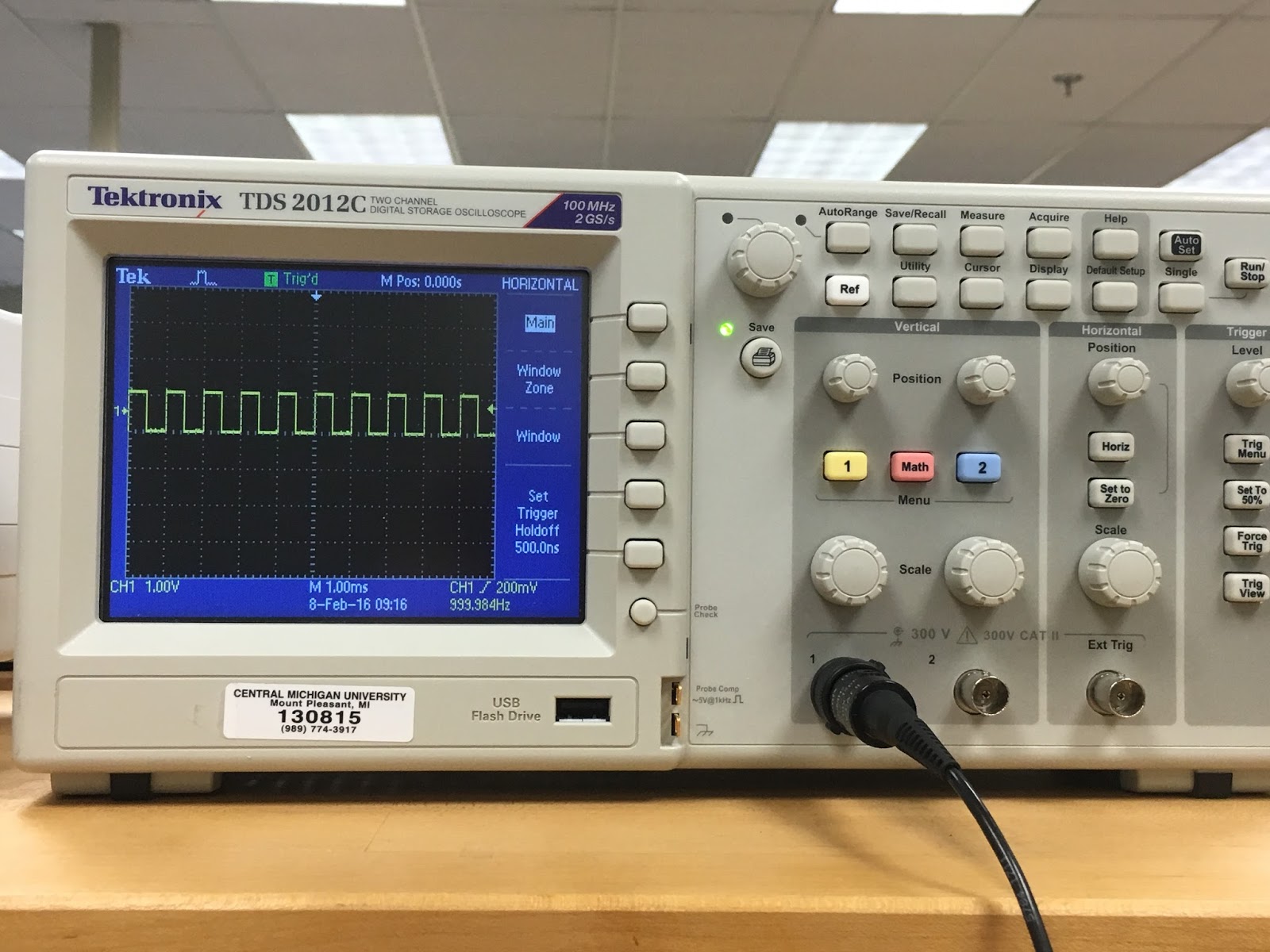
| Image 2: Square wave in display of 5V at 1 kHz. Note: Wave in picture was moving, hence the odd overlapping look |
2. Perform manual probe compensation (Oscilloscope manual page 8) (Photo of overcompensation and proper compensation).
 |
| Image 3: Proper compensation |
 |
| Image 4: Overcompensation |
3.
What does probe attenuation (1x vs 10x) do
(Oscilloscope manual page 9)?
Probe attenuation affects the
vertical scale of the signal. When set to 1X, the probe limits the bandwidth of
the oscilloscope to 7 MHz, while the 10X allows the probe to use the full
bandwidth of the oscilloscope.
4. How do vertical and horizontal controls work? Why would you need it (Oscilloscope manual pages 34-35)?
- The vertical controls shifts the wave up or down
- The horizontal controls shifts the wave to left or right
We need these controls because it adjusts the waveform to what you want. The vertical controls allows you to see the whole wave while the horizontal controls allows you to fixate on a certain section, making it easier to measure one period. You can adjust the functions to give you more than one wave at a time. They can overlap each other or have one wave sit below or above the other wave for comparison.
5.
Generate a 1 kHz, 1 Vpp around a DC 2 V from the
function generator (use the output connector). DO NOT USE oscilloscope probes for the function generator. There is
a separate BNC cable for the function generator.
a.
Connect this to the oscilloscope and verify the
input signal using the horizontal and vertical readings (photo).
b.
Figure out how to measure the signal properties
using menu buttons on the scope.
 |
| Image 5: Our signal with 1 kHz and 1 Vpp around DC 2V |
 |
| Image 6: Amplitude is reading at 0.5 V |
b. When measuring the signal properties, you press Measure, source CH 1, and then press Type to cycle through the properties and find what you want
6.
Connect function generator and oscilloscope
probes switched (red to black, black to red). What happens? Why?
When we did this, we don't get a signal. This occurs because each probe that is grounded is being connected to the other probes, thus grounding the signal.
 |
| Image 7: Oscilloscope showing our finding |
7.
After calibrating the second probe, implement the
voltage divider circuit below. Measure the following voltages using the
Oscilloscope and comment on your results:
We used an amplitude of 0.5 V and an offset of 0.25 V.
We used an amplitude of 0.5 V and an offset of 0.25 V.
 a.
Va and Vb at the same time
(Photo)
a.
Va and Vb at the same time
(Photo)
b.
Voltage across R4.
 |
| Image 8: Two waves at the same time |
b.) For our resistors, we couldn’t find two extra 1k, so we
had use two 820 Ω resistors. We measured the voltage across R4 to be 233 mV-118mV = 115 mV
8.
For the same circuit above, measure Va
and Vb using the handheld DMM both in AC and DC mode. What are your
findings? Explain.
In AC:
Va
|
Vb
|
111.7 mV
|
224.4 mV
|
In DC:
Va
|
Vb
|
15.9 mV
|
31.8 mV
|
For AC, we applied 0.5 V peak to peak, seeing that the maximum applied voltage of AV is 0.25 V. For DC, the voltage should've been split evenly among the two resistors because they have the same resistance.
9.
For the circuit below
a.
Calculate R so given voltage values are
satisfied. Explain your work (video)
b.
Construct the circuit and measure the values
with the DMM and oscilloscope (video). Hint: 1kΩ cannot be probed directly by
the scope. But R6 and R7 are in series and it does not matter which one is
connected to the function generator.

a.
Video 1: Calculating R
Video 2: Measuring with the DMM and Oscilloscope
10. Operational amplifier basics: Construct the following circuits using the pin diagram of the opamp. The half circle on top of the pin diagram corresponds to the notch on the integrated circuit (IC). Explanations of the pin numbers are below:
1: DO NOT USE
|
8: DO NOT USE
|
2: Negative input
|
7: +10V
|
3: Positive input
|
6: output
|
4: -10 V
|
5: DO NOT USE
|

a.
Inverting amplifier: Rin = 1kΩ, Rf
= 5kΩ (do not forget -10 V and +10
V). Apply 1 Vpp @ 1kHz. Observe input and output at the same time.
What happens if you slowly increase the input voltage up to 5 V? Explain your
findings. (Video)
Video 3: Inverting Amplifier
b.
Non-inverting amplifier: R1 = 1kΩ, R2
= 5kΩ (do not forget -10 V and +10
V). Apply 1 Vpp @ 1kHz. Observe input and output at the same time.
What happens if you slowly increase the input voltage up to 5 V? Explain your
findings. (Video)
Video 4: Non-inverting Amplifier
I like all of the photos you have on you blog.
ReplyDelete#3 has some missing information.
ReplyDelete#8: Are AC and DC calculations related?